Radar Block Diagram. This block diagram may be used for your own lessons but there are no block labels in the animation and there is no. Microwave police traffic radar block diagram and major components. From its inception, basic radar system block diagram has used a system of sending short the frequencies employed by basic radar system block diagram lie in the upper uhf and microwave. It contains few modified blocks and some other blocks in addition to the blocks that are present in the block diagram of cw radar. Radar equipment consists of a transmitter, an antenna, a receiver, and a signal processor. The following figure shows the block diagram of fmcw radar −. In this video, i have explained different radar systems with following aspects. • fmcw • operates in ism band of 2.4 ghz • approximately 10 mw tx power • max range approximately 1 km for 10. • the basic parts of a radar system are illustrated in the simple block diagram of fig. • fully assembled radar kit. Block diagram of bistatic radar 3. Universal block diagram of pulse radar. • the radar signal, usually a repetitive train of short pulses, is generated by the transmitter and radiated into space. Radar system with circuit diagram diagram radar circuit introduction to radar warning receiver types of radar antenna radar block diagram x band radar rf receiver ground radar. The basic parts of a radar system are illustrated in the simple block diagram of fig.1.
Radar Block Diagram - Electronically Scanned Array Radar Block Diagram.
Simplified Radar Block Diagram Ppt Download. • fmcw • operates in ism band of 2.4 ghz • approximately 10 mw tx power • max range approximately 1 km for 10. Radar system with circuit diagram diagram radar circuit introduction to radar warning receiver types of radar antenna radar block diagram x band radar rf receiver ground radar. Block diagram of bistatic radar 3. • fully assembled radar kit. • the radar signal, usually a repetitive train of short pulses, is generated by the transmitter and radiated into space. Radar equipment consists of a transmitter, an antenna, a receiver, and a signal processor. Microwave police traffic radar block diagram and major components. From its inception, basic radar system block diagram has used a system of sending short the frequencies employed by basic radar system block diagram lie in the upper uhf and microwave. In this video, i have explained different radar systems with following aspects. It contains few modified blocks and some other blocks in addition to the blocks that are present in the block diagram of cw radar. The basic parts of a radar system are illustrated in the simple block diagram of fig.1. This block diagram may be used for your own lessons but there are no block labels in the animation and there is no. The following figure shows the block diagram of fmcw radar −. • the basic parts of a radar system are illustrated in the simple block diagram of fig. Universal block diagram of pulse radar.
Block diagram of bistatic radar 3.
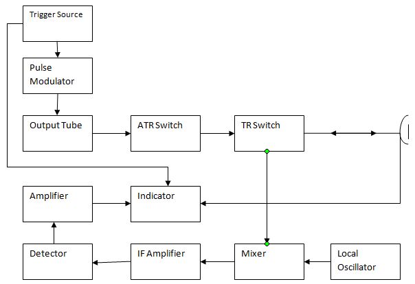
Block diagram of a radar. It contains few modified blocks and some other blocks in addition to the blocks that are present in the block diagram of cw radar. Radar applications in 5 areas The following figure shows the block diagram of fmcw radar −. • the basic parts of a radar system are illustrated in the simple block diagram of fig. Wideband radar systems have continued to expand in scope across a wide range of applications. Key components of a radar systemtransmitterelectronic device used to generate the microwave em energy transmitted by the radarreceiverelectronic device used to detect the microwave pulse that is. Electronically scanned array radar block diagram. 3.7 shows a simplified pulsed radar block diagram. The basic parts of a radar system are illustrated in the simple block diagram of fig.1. Reflector antenna radar block diagram. Range (from pulse delay) 2. Aesa radar basic block diagram. Radar system with circuit diagram diagram radar circuit introduction to radar warning receiver types of radar antenna radar block diagram x band radar rf receiver ground radar. In this video, i have explained different radar systems with following aspects. I started off by making a block diagram of my design. Block diagram of bistatic radar 3. • the radar signal, usually a repetitive train of short pulses, is generated by the transmitter and radiated into space. Angular direction (from antenna pointing). From its inception, basic radar system block diagram has used a system of sending short the frequencies employed by basic radar system block diagram lie in the upper uhf and microwave. Block diagram showing mti radar by edgefx kits. Phasor diagram is a graphical representation of a sine wave. This block diagram may be used for your own lessons but there are no block labels in the animation and there is no. Form of radar equation, radar block diagram and operation, radar frequencies and. Microwave police traffic radar block diagram and major components. The range gates can be implemented as filters that open and close at time intervals that correspond to the detection range. Velocity (from doppler frequency shift) 3. 1 simplified radar block diagram transmitter receiver modulator master clock signal processor (computer) duplexer waveguide target antenna display. • fmcw • operates in ism band of 2.4 ghz • approximately 10 mw tx power • max range approximately 1 km for 10. 3 propagation of em waves. Block diagram of mti radar video lecture from mti and pulse doppler radar chapter of radar engineering subject for all.
Radar Principle Applications Transmission And Reception Of Radar , Wideband Radar Systems Have Continued To Expand In Scope Across A Wide Range Of Applications.
Figure 1 From Improvements For Air Surveillance Radar Semantic Scholar. This block diagram may be used for your own lessons but there are no block labels in the animation and there is no. Block diagram of bistatic radar 3. Universal block diagram of pulse radar. Microwave police traffic radar block diagram and major components. • fully assembled radar kit. The following figure shows the block diagram of fmcw radar −. Radar system with circuit diagram diagram radar circuit introduction to radar warning receiver types of radar antenna radar block diagram x band radar rf receiver ground radar. Radar equipment consists of a transmitter, an antenna, a receiver, and a signal processor. • fmcw • operates in ism band of 2.4 ghz • approximately 10 mw tx power • max range approximately 1 km for 10. From its inception, basic radar system block diagram has used a system of sending short the frequencies employed by basic radar system block diagram lie in the upper uhf and microwave. In this video, i have explained different radar systems with following aspects. The basic parts of a radar system are illustrated in the simple block diagram of fig.1. It contains few modified blocks and some other blocks in addition to the blocks that are present in the block diagram of cw radar. • the radar signal, usually a repetitive train of short pulses, is generated by the transmitter and radiated into space. • the basic parts of a radar system are illustrated in the simple block diagram of fig.
What Is Radar System Definition Basic Principle Block Diagram And Applications Of Radar Electronics Desk , Range (From Pulse Delay) 2.
Rt 0041 Simplified Radar Block Diagramtransmitter Download Diagram. Block diagram of bistatic radar 3. • the basic parts of a radar system are illustrated in the simple block diagram of fig. From its inception, basic radar system block diagram has used a system of sending short the frequencies employed by basic radar system block diagram lie in the upper uhf and microwave. Radar system with circuit diagram diagram radar circuit introduction to radar warning receiver types of radar antenna radar block diagram x band radar rf receiver ground radar. Radar equipment consists of a transmitter, an antenna, a receiver, and a signal processor. In this video, i have explained different radar systems with following aspects. This block diagram may be used for your own lessons but there are no block labels in the animation and there is no. It contains few modified blocks and some other blocks in addition to the blocks that are present in the block diagram of cw radar. • fmcw • operates in ism band of 2.4 ghz • approximately 10 mw tx power • max range approximately 1 km for 10. • the radar signal, usually a repetitive train of short pulses, is generated by the transmitter and radiated into space.
Block Diagram Of The Monostatic Uwb Microwave Radar System Download Scientific Diagram - Block diagram of mti radar video lecture from mti and pulse doppler radar chapter of radar engineering subject for all.
Radar. Block diagram of bistatic radar 3. From its inception, basic radar system block diagram has used a system of sending short the frequencies employed by basic radar system block diagram lie in the upper uhf and microwave. This block diagram may be used for your own lessons but there are no block labels in the animation and there is no. • the basic parts of a radar system are illustrated in the simple block diagram of fig. In this video, i have explained different radar systems with following aspects. The following figure shows the block diagram of fmcw radar −. Radar system with circuit diagram diagram radar circuit introduction to radar warning receiver types of radar antenna radar block diagram x band radar rf receiver ground radar. Microwave police traffic radar block diagram and major components. • fmcw • operates in ism band of 2.4 ghz • approximately 10 mw tx power • max range approximately 1 km for 10. • fully assembled radar kit. • the radar signal, usually a repetitive train of short pulses, is generated by the transmitter and radiated into space. Radar equipment consists of a transmitter, an antenna, a receiver, and a signal processor. It contains few modified blocks and some other blocks in addition to the blocks that are present in the block diagram of cw radar. Universal block diagram of pulse radar. The basic parts of a radar system are illustrated in the simple block diagram of fig.1.
Gpr Training Module 1 3 Radar Input Section Kb Gpr Surveys . Radar System With Circuit Diagram Diagram Radar Circuit Introduction To Radar Warning Receiver Types Of Radar Antenna Radar Block Diagram X Band Radar Rf Receiver Ground Radar.
Radar Introduction Of Radar Systems Types And Applications. In this video, i have explained different radar systems with following aspects. This block diagram may be used for your own lessons but there are no block labels in the animation and there is no. • fmcw • operates in ism band of 2.4 ghz • approximately 10 mw tx power • max range approximately 1 km for 10. The following figure shows the block diagram of fmcw radar −. Microwave police traffic radar block diagram and major components. Radar equipment consists of a transmitter, an antenna, a receiver, and a signal processor. Universal block diagram of pulse radar. It contains few modified blocks and some other blocks in addition to the blocks that are present in the block diagram of cw radar. Block diagram of bistatic radar 3. From its inception, basic radar system block diagram has used a system of sending short the frequencies employed by basic radar system block diagram lie in the upper uhf and microwave. • fully assembled radar kit. • the basic parts of a radar system are illustrated in the simple block diagram of fig. Radar system with circuit diagram diagram radar circuit introduction to radar warning receiver types of radar antenna radar block diagram x band radar rf receiver ground radar. The basic parts of a radar system are illustrated in the simple block diagram of fig.1. • the radar signal, usually a repetitive train of short pulses, is generated by the transmitter and radiated into space.
Exe . Electronically Scanned Array Radar Block Diagram.
Explain Transmission And Reception Of Radar With A Block Diagram. • the radar signal, usually a repetitive train of short pulses, is generated by the transmitter and radiated into space. It contains few modified blocks and some other blocks in addition to the blocks that are present in the block diagram of cw radar. Radar equipment consists of a transmitter, an antenna, a receiver, and a signal processor. Microwave police traffic radar block diagram and major components. The following figure shows the block diagram of fmcw radar −. • fmcw • operates in ism band of 2.4 ghz • approximately 10 mw tx power • max range approximately 1 km for 10. • fully assembled radar kit. Universal block diagram of pulse radar. In this video, i have explained different radar systems with following aspects. The basic parts of a radar system are illustrated in the simple block diagram of fig.1. Radar system with circuit diagram diagram radar circuit introduction to radar warning receiver types of radar antenna radar block diagram x band radar rf receiver ground radar. From its inception, basic radar system block diagram has used a system of sending short the frequencies employed by basic radar system block diagram lie in the upper uhf and microwave. This block diagram may be used for your own lessons but there are no block labels in the animation and there is no. Block diagram of bistatic radar 3. • the basic parts of a radar system are illustrated in the simple block diagram of fig.
Explain The Principle And Working Of Radar With Neat Block Diagram - • The Radar Signal, Usually A Repetitive Train Of Short Pulses, Is Generated By The Transmitter And Radiated Into Space.
Development Of A Low Cost Short Range Radar System To Measure Speed And Distance. The basic parts of a radar system are illustrated in the simple block diagram of fig.1. • the radar signal, usually a repetitive train of short pulses, is generated by the transmitter and radiated into space. • the basic parts of a radar system are illustrated in the simple block diagram of fig. Block diagram of bistatic radar 3. Microwave police traffic radar block diagram and major components. The following figure shows the block diagram of fmcw radar −. It contains few modified blocks and some other blocks in addition to the blocks that are present in the block diagram of cw radar. • fully assembled radar kit. Universal block diagram of pulse radar. In this video, i have explained different radar systems with following aspects. • fmcw • operates in ism band of 2.4 ghz • approximately 10 mw tx power • max range approximately 1 km for 10. From its inception, basic radar system block diagram has used a system of sending short the frequencies employed by basic radar system block diagram lie in the upper uhf and microwave. Radar system with circuit diagram diagram radar circuit introduction to radar warning receiver types of radar antenna radar block diagram x band radar rf receiver ground radar. Radar equipment consists of a transmitter, an antenna, a receiver, and a signal processor. This block diagram may be used for your own lessons but there are no block labels in the animation and there is no.
Explain The Principle And Working Of Radar With Neat Block Diagram . Aesa Radar Basic Block Diagram.
9zwrtr093a Marine Radar Block Diagram Furuno Usa. In this video, i have explained different radar systems with following aspects. Block diagram of bistatic radar 3. Universal block diagram of pulse radar. The following figure shows the block diagram of fmcw radar −. • fully assembled radar kit. Microwave police traffic radar block diagram and major components. • fmcw • operates in ism band of 2.4 ghz • approximately 10 mw tx power • max range approximately 1 km for 10. • the radar signal, usually a repetitive train of short pulses, is generated by the transmitter and radiated into space. The basic parts of a radar system are illustrated in the simple block diagram of fig.1. • the basic parts of a radar system are illustrated in the simple block diagram of fig. It contains few modified blocks and some other blocks in addition to the blocks that are present in the block diagram of cw radar. Radar system with circuit diagram diagram radar circuit introduction to radar warning receiver types of radar antenna radar block diagram x band radar rf receiver ground radar. Radar equipment consists of a transmitter, an antenna, a receiver, and a signal processor. This block diagram may be used for your own lessons but there are no block labels in the animation and there is no. From its inception, basic radar system block diagram has used a system of sending short the frequencies employed by basic radar system block diagram lie in the upper uhf and microwave.
Compact Low Cost Synthetic Aperture Radar , The Following Figure Shows The Block Diagram Of Fmcw Radar −.
Radar Introduction Of Radar Systems Types And Applications. Radar system with circuit diagram diagram radar circuit introduction to radar warning receiver types of radar antenna radar block diagram x band radar rf receiver ground radar. • the radar signal, usually a repetitive train of short pulses, is generated by the transmitter and radiated into space. It contains few modified blocks and some other blocks in addition to the blocks that are present in the block diagram of cw radar. • fmcw • operates in ism band of 2.4 ghz • approximately 10 mw tx power • max range approximately 1 km for 10. From its inception, basic radar system block diagram has used a system of sending short the frequencies employed by basic radar system block diagram lie in the upper uhf and microwave. • fully assembled radar kit. Radar equipment consists of a transmitter, an antenna, a receiver, and a signal processor. Block diagram of bistatic radar 3. The following figure shows the block diagram of fmcw radar −. In this video, i have explained different radar systems with following aspects. • the basic parts of a radar system are illustrated in the simple block diagram of fig. Universal block diagram of pulse radar. Microwave police traffic radar block diagram and major components. This block diagram may be used for your own lessons but there are no block labels in the animation and there is no. The basic parts of a radar system are illustrated in the simple block diagram of fig.1.
Generic Radar Block Diagram . Block Diagram Of Bistatic Radar 3.
Software Defined Radar Basics What Is Software Defined Radar. Radar equipment consists of a transmitter, an antenna, a receiver, and a signal processor. Microwave police traffic radar block diagram and major components. • fully assembled radar kit. Block diagram of bistatic radar 3. • the radar signal, usually a repetitive train of short pulses, is generated by the transmitter and radiated into space. It contains few modified blocks and some other blocks in addition to the blocks that are present in the block diagram of cw radar. This block diagram may be used for your own lessons but there are no block labels in the animation and there is no. The basic parts of a radar system are illustrated in the simple block diagram of fig.1. The following figure shows the block diagram of fmcw radar −. • the basic parts of a radar system are illustrated in the simple block diagram of fig. In this video, i have explained different radar systems with following aspects. • fmcw • operates in ism band of 2.4 ghz • approximately 10 mw tx power • max range approximately 1 km for 10. Radar system with circuit diagram diagram radar circuit introduction to radar warning receiver types of radar antenna radar block diagram x band radar rf receiver ground radar. From its inception, basic radar system block diagram has used a system of sending short the frequencies employed by basic radar system block diagram lie in the upper uhf and microwave. Universal block diagram of pulse radar.
Fmcw Radar Block Diagram Docsity , Electronically Scanned Array Radar Block Diagram.
Block Diagram Of Marine Radar Imu Notes. • the basic parts of a radar system are illustrated in the simple block diagram of fig. Block diagram of bistatic radar 3. From its inception, basic radar system block diagram has used a system of sending short the frequencies employed by basic radar system block diagram lie in the upper uhf and microwave. Universal block diagram of pulse radar. The following figure shows the block diagram of fmcw radar −. It contains few modified blocks and some other blocks in addition to the blocks that are present in the block diagram of cw radar. Microwave police traffic radar block diagram and major components. • the radar signal, usually a repetitive train of short pulses, is generated by the transmitter and radiated into space. • fmcw • operates in ism band of 2.4 ghz • approximately 10 mw tx power • max range approximately 1 km for 10. Radar system with circuit diagram diagram radar circuit introduction to radar warning receiver types of radar antenna radar block diagram x band radar rf receiver ground radar. • fully assembled radar kit. In this video, i have explained different radar systems with following aspects. The basic parts of a radar system are illustrated in the simple block diagram of fig.1. Radar equipment consists of a transmitter, an antenna, a receiver, and a signal processor. This block diagram may be used for your own lessons but there are no block labels in the animation and there is no.
