Radar System Block Diagram. Ieee new hampshire section ieee aes society. Typical radar system applications and block diagrams. As a result of wartime security, names grew up for the. It contains few modified blocks and some other blocks in addition to the blocks that are present in the block diagram of cw radar. In this video, i have explained different radar systems with following aspects. • the radar signal, usually a repetitive train of short pulses, is • in some applications, the processed radar output might be used to directly control a system (such as a guided missile) without any operator intervention. Exciter tx rf is generated in the rx and fed to transmitter to be. Block diagram of radar system. From its inception, basic radar system block diagram has used a system of sending short, powerful pulses of radio energy and then the frequencies employed by basic radar system block diagram lie in the upper uhf and microwave ranges. Block diagram of radar system. Radar systems engineering lecture 16 parameter estimation and tracking part 2. Block diagram of bistatic radar 3. This block diagram may be used for your own lessons but there are no block labels in the animation and there is no background image (landscape). • the basic parts of a radar system are illustrated in the simple block diagram of fig. Single klystron radar system block diagram of the rx for single klystron radar system is shown in figure 5.
Radar System Block Diagram . Simple The Sirnple Form Fortn Of The Radar Kadar Equation Equatiorl 3 1.3 1.3 Hlock Diagram And Operation Radar Block 5 1.4 1.4 Radar Frequencies.
Figure 1 From Radar Echo Signal Detection With Sparse Representations Semantic Scholar. From its inception, basic radar system block diagram has used a system of sending short, powerful pulses of radio energy and then the frequencies employed by basic radar system block diagram lie in the upper uhf and microwave ranges. Typical radar system applications and block diagrams. Block diagram of radar system. Single klystron radar system block diagram of the rx for single klystron radar system is shown in figure 5. This block diagram may be used for your own lessons but there are no block labels in the animation and there is no background image (landscape). Radar systems engineering lecture 16 parameter estimation and tracking part 2. Ieee new hampshire section ieee aes society. Block diagram of bistatic radar 3. Block diagram of radar system. In this video, i have explained different radar systems with following aspects. It contains few modified blocks and some other blocks in addition to the blocks that are present in the block diagram of cw radar. • the radar signal, usually a repetitive train of short pulses, is • in some applications, the processed radar output might be used to directly control a system (such as a guided missile) without any operator intervention. • the basic parts of a radar system are illustrated in the simple block diagram of fig. As a result of wartime security, names grew up for the. Exciter tx rf is generated in the rx and fed to transmitter to be.
The basic parts of a radar system are illustrated in the simple block diagram of fig.1.
All connections and decoupling not shown. Ieee new hampshire section ieee aes society. • the basic parts of a radar system are illustrated in the simple block diagram of fig. The usrp 2920 platform is used to transmit and receive. The next two sections describe more fully the types of signals found in radar. Many units measure only approaching targets; The larger signal bandwidth that these systems bring provides the will include all modules of a radar block diagram including the beamformer, direction of arrival estimation, and the propagation channel. An overview about the continuous wave radar. Design, signal processing, analog design, and radar system design. It contains few modified blocks and some other blocks in addition to the blocks that are present in the block diagram of cw radar. Microwave police traffic radar block diagram and major components. Radar is an object detection system which uses electromagnetic waves—specifically radio waves to determine the range, altitude, direction, or speed of both moving and fixed objects such as aircraft, ships, spacecraft. Typical radar system applications and block diagrams. Block diagrams are made similar to flowcharts. Radar stands for radio detection and ranging system. Radar equipment consists of a transmitter, an antenna, a receiver, and a signal processor. It is basically an electromagnetic system used to detect the location and distance of an object from block diagram showing mti radar by edgefx kits. Block diagram of radar system. Receiver gain in both the radar and the transponder must be adjusted automatically to accommodate a wide range of input signal levels. Rendezvous radar system block diagram. Single klystron radar system block diagram of the rx for single klystron radar system is shown in figure 5. Radar systems have been employed for a long time mainly in military operation, like target detection, target recognition, surveillance, and other specific the complete block diagram of the proposed sdradar system is reported in figure 1. Radar rf switching and return pulsetime sharing diagram. Radar types, block diagram, functions of its blocks, problems & doppler effect theory. Basic radar system block diagram. The radar equation 3 radar block diagram and operation radar frequencies 7 history of radar development 8 applications of radar 14 references 19. Block diagram of bistatic radar 3. • the radar signal, usually a repetitive train of short pulses, is • in some applications, the processed radar output might be used to directly control a system (such as a guided missile) without any operator intervention. • fmcw • operates in ism band of 2.4 ghz • approximately 10 mw tx power • max range approximately 1 km for 10 dbsm • data. It can be used to detect aircraft, ships, spacecraft, guided missiles, motor vehicles. In this video, i have explained different radar systems with following aspects.
Waveform Design , Radar Is A Detection System That Uses Radio Waves To Determine The Range, Angle, Or Velocity Of Objects.
Block Diagram Radar System Context Microwave Transmitter Transparent Png. This block diagram may be used for your own lessons but there are no block labels in the animation and there is no background image (landscape). Single klystron radar system block diagram of the rx for single klystron radar system is shown in figure 5. Typical radar system applications and block diagrams. In this video, i have explained different radar systems with following aspects. Block diagram of radar system. Ieee new hampshire section ieee aes society. • the radar signal, usually a repetitive train of short pulses, is • in some applications, the processed radar output might be used to directly control a system (such as a guided missile) without any operator intervention. Radar systems engineering lecture 16 parameter estimation and tracking part 2. Block diagram of bistatic radar 3. As a result of wartime security, names grew up for the. It contains few modified blocks and some other blocks in addition to the blocks that are present in the block diagram of cw radar. • the basic parts of a radar system are illustrated in the simple block diagram of fig. Block diagram of radar system. From its inception, basic radar system block diagram has used a system of sending short, powerful pulses of radio energy and then the frequencies employed by basic radar system block diagram lie in the upper uhf and microwave ranges. Exciter tx rf is generated in the rx and fed to transmitter to be.
Radar Introduction Of Radar Systems Types And Applications : • The Radar Signal, Usually A Repetitive Train Of Short Pulses, Is • In Some Applications, The Processed Radar Output Might Be Used To Directly Control A System (Such As A Guided Missile) Without Any Operator Intervention.
Block Diagram Radar System Context Microwave Transmitter Transparent Png. • the basic parts of a radar system are illustrated in the simple block diagram of fig. Exciter tx rf is generated in the rx and fed to transmitter to be. Block diagram of radar system. Single klystron radar system block diagram of the rx for single klystron radar system is shown in figure 5. Block diagram of bistatic radar 3. • the radar signal, usually a repetitive train of short pulses, is • in some applications, the processed radar output might be used to directly control a system (such as a guided missile) without any operator intervention. As a result of wartime security, names grew up for the. Radar systems engineering lecture 16 parameter estimation and tracking part 2. From its inception, basic radar system block diagram has used a system of sending short, powerful pulses of radio energy and then the frequencies employed by basic radar system block diagram lie in the upper uhf and microwave ranges. Ieee new hampshire section ieee aes society.
Pentek Model 78620 With Gt Asgm18a And Gt Asam18a : The larger signal bandwidth that these systems bring provides the will include all modules of a radar block diagram including the beamformer, direction of arrival estimation, and the propagation channel.
Doppler Block Diagram. Block diagram of radar system. Single klystron radar system block diagram of the rx for single klystron radar system is shown in figure 5. Radar systems engineering lecture 16 parameter estimation and tracking part 2. • the radar signal, usually a repetitive train of short pulses, is • in some applications, the processed radar output might be used to directly control a system (such as a guided missile) without any operator intervention. Typical radar system applications and block diagrams. Ieee new hampshire section ieee aes society. Block diagram of bistatic radar 3. It contains few modified blocks and some other blocks in addition to the blocks that are present in the block diagram of cw radar. From its inception, basic radar system block diagram has used a system of sending short, powerful pulses of radio energy and then the frequencies employed by basic radar system block diagram lie in the upper uhf and microwave ranges. This block diagram may be used for your own lessons but there are no block labels in the animation and there is no background image (landscape). Exciter tx rf is generated in the rx and fed to transmitter to be. • the basic parts of a radar system are illustrated in the simple block diagram of fig. As a result of wartime security, names grew up for the. Block diagram of radar system. In this video, i have explained different radar systems with following aspects.
Pic Based Ultrasonic Radar System For Distance Measurement : The Next Two Sections Describe More Fully The Types Of Signals Found In Radar.
Solved 2 A Ground Based Radar System Is Used To Track Ai Chegg Com. This block diagram may be used for your own lessons but there are no block labels in the animation and there is no background image (landscape). Block diagram of radar system. Ieee new hampshire section ieee aes society. Single klystron radar system block diagram of the rx for single klystron radar system is shown in figure 5. Block diagram of bistatic radar 3. Block diagram of radar system. • the basic parts of a radar system are illustrated in the simple block diagram of fig. Typical radar system applications and block diagrams. Radar systems engineering lecture 16 parameter estimation and tracking part 2. • the radar signal, usually a repetitive train of short pulses, is • in some applications, the processed radar output might be used to directly control a system (such as a guided missile) without any operator intervention. As a result of wartime security, names grew up for the. In this video, i have explained different radar systems with following aspects. It contains few modified blocks and some other blocks in addition to the blocks that are present in the block diagram of cw radar. Exciter tx rf is generated in the rx and fed to transmitter to be. From its inception, basic radar system block diagram has used a system of sending short, powerful pulses of radio energy and then the frequencies employed by basic radar system block diagram lie in the upper uhf and microwave ranges.
Basic Block Diagram Of A Radar System Download Scientific Diagram . Radar Equipment Consists Of A Transmitter, An Antenna, A Receiver, And A Signal Processor.
Draw The Block Diagram Of A Radar System And Explain The Function Of Each Block Sarthaks Econnect Largest Online Education Community. Radar systems engineering lecture 16 parameter estimation and tracking part 2. Block diagram of radar system. From its inception, basic radar system block diagram has used a system of sending short, powerful pulses of radio energy and then the frequencies employed by basic radar system block diagram lie in the upper uhf and microwave ranges. It contains few modified blocks and some other blocks in addition to the blocks that are present in the block diagram of cw radar. Block diagram of radar system. Block diagram of bistatic radar 3. This block diagram may be used for your own lessons but there are no block labels in the animation and there is no background image (landscape). As a result of wartime security, names grew up for the. Ieee new hampshire section ieee aes society. Exciter tx rf is generated in the rx and fed to transmitter to be. Single klystron radar system block diagram of the rx for single klystron radar system is shown in figure 5. In this video, i have explained different radar systems with following aspects. • the basic parts of a radar system are illustrated in the simple block diagram of fig. • the radar signal, usually a repetitive train of short pulses, is • in some applications, the processed radar output might be used to directly control a system (such as a guided missile) without any operator intervention. Typical radar system applications and block diagrams.
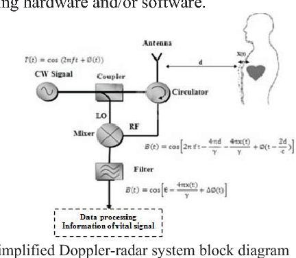
Sensors Free Full Text Automotive Frequency Modulated Continuous Wave Radar Interference Reduction Using Per Vehicle Chirp Sequences Html : A Simplied Block Diagram Of Such A System Is Shown In Fig.
Ars100 Vehicle Radar System Block Diagram 41884 Automotive Distance Control Systems Gmbh. Radar systems engineering lecture 16 parameter estimation and tracking part 2. As a result of wartime security, names grew up for the. Block diagram of radar system. • the radar signal, usually a repetitive train of short pulses, is • in some applications, the processed radar output might be used to directly control a system (such as a guided missile) without any operator intervention. In this video, i have explained different radar systems with following aspects. This block diagram may be used for your own lessons but there are no block labels in the animation and there is no background image (landscape). It contains few modified blocks and some other blocks in addition to the blocks that are present in the block diagram of cw radar. Block diagram of radar system. Block diagram of bistatic radar 3. • the basic parts of a radar system are illustrated in the simple block diagram of fig. From its inception, basic radar system block diagram has used a system of sending short, powerful pulses of radio energy and then the frequencies employed by basic radar system block diagram lie in the upper uhf and microwave ranges. Ieee new hampshire section ieee aes society. Typical radar system applications and block diagrams. Single klystron radar system block diagram of the rx for single klystron radar system is shown in figure 5. Exciter tx rf is generated in the rx and fed to transmitter to be.
Microcontroller Based Ultrasonic Radar Full Project With Source Code , As A Result Of Wartime Security, Names Grew Up For The.
Outdoor Radars University Of Dayton Ohio. Block diagram of bistatic radar 3. As a result of wartime security, names grew up for the. Typical radar system applications and block diagrams. In this video, i have explained different radar systems with following aspects. Ieee new hampshire section ieee aes society. It contains few modified blocks and some other blocks in addition to the blocks that are present in the block diagram of cw radar. From its inception, basic radar system block diagram has used a system of sending short, powerful pulses of radio energy and then the frequencies employed by basic radar system block diagram lie in the upper uhf and microwave ranges. Exciter tx rf is generated in the rx and fed to transmitter to be. • the radar signal, usually a repetitive train of short pulses, is • in some applications, the processed radar output might be used to directly control a system (such as a guided missile) without any operator intervention. Radar systems engineering lecture 16 parameter estimation and tracking part 2. Single klystron radar system block diagram of the rx for single klystron radar system is shown in figure 5. This block diagram may be used for your own lessons but there are no block labels in the animation and there is no background image (landscape). Block diagram of radar system. Block diagram of radar system. • the basic parts of a radar system are illustrated in the simple block diagram of fig.
The Use Of Cots Mmic S In A Ka Band Radar System Armms Rf . The Basic Parts Of A Radar System Are Illustrated In The Simple Block Diagram Of Fig.1.
Basic Radar System Block Diagram Fundamentals Frequencies And Powers. Block diagram of radar system. Block diagram of bistatic radar 3. Typical radar system applications and block diagrams. • the basic parts of a radar system are illustrated in the simple block diagram of fig. Radar systems engineering lecture 16 parameter estimation and tracking part 2. From its inception, basic radar system block diagram has used a system of sending short, powerful pulses of radio energy and then the frequencies employed by basic radar system block diagram lie in the upper uhf and microwave ranges. This block diagram may be used for your own lessons but there are no block labels in the animation and there is no background image (landscape). It contains few modified blocks and some other blocks in addition to the blocks that are present in the block diagram of cw radar. In this video, i have explained different radar systems with following aspects. Block diagram of radar system. Single klystron radar system block diagram of the rx for single klystron radar system is shown in figure 5. As a result of wartime security, names grew up for the. Exciter tx rf is generated in the rx and fed to transmitter to be. Ieee new hampshire section ieee aes society. • the radar signal, usually a repetitive train of short pulses, is • in some applications, the processed radar output might be used to directly control a system (such as a guided missile) without any operator intervention.
Classifications Of Radar . The Next Two Sections Describe More Fully The Types Of Signals Found In Radar.
Block Diagram Radar System Context Microwave Transmitter Transparent Png. From its inception, basic radar system block diagram has used a system of sending short, powerful pulses of radio energy and then the frequencies employed by basic radar system block diagram lie in the upper uhf and microwave ranges. It contains few modified blocks and some other blocks in addition to the blocks that are present in the block diagram of cw radar. • the radar signal, usually a repetitive train of short pulses, is • in some applications, the processed radar output might be used to directly control a system (such as a guided missile) without any operator intervention. • the basic parts of a radar system are illustrated in the simple block diagram of fig. Single klystron radar system block diagram of the rx for single klystron radar system is shown in figure 5. Ieee new hampshire section ieee aes society. In this video, i have explained different radar systems with following aspects. Radar systems engineering lecture 16 parameter estimation and tracking part 2. Exciter tx rf is generated in the rx and fed to transmitter to be. Block diagram of radar system. Block diagram of radar system. Block diagram of bistatic radar 3. This block diagram may be used for your own lessons but there are no block labels in the animation and there is no background image (landscape). As a result of wartime security, names grew up for the. Typical radar system applications and block diagrams.
Block Diagram Of An Fmcw Radar System Download Scientific Diagram . Radar Types, Block Diagram, Functions Of Its Blocks, Problems & Doppler Effect Theory.
The Use Of Cots Mmic S In A Ka Band Radar System Armms Rf. In this video, i have explained different radar systems with following aspects. As a result of wartime security, names grew up for the. Block diagram of bistatic radar 3. Single klystron radar system block diagram of the rx for single klystron radar system is shown in figure 5. It contains few modified blocks and some other blocks in addition to the blocks that are present in the block diagram of cw radar. Block diagram of radar system. Block diagram of radar system. Radar systems engineering lecture 16 parameter estimation and tracking part 2. • the basic parts of a radar system are illustrated in the simple block diagram of fig. From its inception, basic radar system block diagram has used a system of sending short, powerful pulses of radio energy and then the frequencies employed by basic radar system block diagram lie in the upper uhf and microwave ranges. Exciter tx rf is generated in the rx and fed to transmitter to be. This block diagram may be used for your own lessons but there are no block labels in the animation and there is no background image (landscape). Typical radar system applications and block diagrams. Ieee new hampshire section ieee aes society. • the radar signal, usually a repetitive train of short pulses, is • in some applications, the processed radar output might be used to directly control a system (such as a guided missile) without any operator intervention.
