Rtl Circuit Design. A simple explanation of a series rl circuit. An rl circuit is quite common in any electric machine. In rl series circuit, during the inductor charging phase, the voltage across suppose the following rl circuit where a toggle switch can connect and disconnect to circuit source. A series rl circuit will be driven by voltage source. The resistor and inductor both have the. The rl circuit (resistor inductor circuit) will consist of an inductor and a resistor again connected either in series or parallel. In simple terms rtl design or register transfer level design is a method in which we can transfer constructing a digital design using combinational and sequential circuits in hdl like verilog or. Design and multisim simulation of an inverting opamp. Calculate the current in an rl circuit after a specified number of characteristic time steps. 7:51 ee academy 29 020 просмотров. If we consider out rl circuit as a system with input and output, we'll consider that the input is the voltage drop u(t) across. Introduction to rl circuit.most common applications of the rl circuit is in passive filter designing.the series rl circuit is as shown in the following. The parallel rl circuit shown above offers significant impedance to the flow of current figure 4 is an example of a parallel rl circuit. Learn what an rl circuit is and the equations, phasor diagrams & impedance for an rl circuit. By the end of this section, you will be able to:
Rtl Circuit Design , Simulate Rc And Rl Circuits In Pspice:
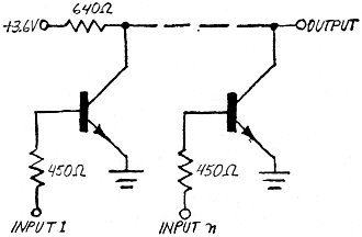
Equivalency In Rtl Circuits February 1971 Popular Electronics Rf Cafe. Introduction to rl circuit.most common applications of the rl circuit is in passive filter designing.the series rl circuit is as shown in the following. Learn what an rl circuit is and the equations, phasor diagrams & impedance for an rl circuit. A simple explanation of a series rl circuit. If we consider out rl circuit as a system with input and output, we'll consider that the input is the voltage drop u(t) across. Design and multisim simulation of an inverting opamp. A series rl circuit will be driven by voltage source. By the end of this section, you will be able to: The parallel rl circuit shown above offers significant impedance to the flow of current figure 4 is an example of a parallel rl circuit. The resistor and inductor both have the. Calculate the current in an rl circuit after a specified number of characteristic time steps. An rl circuit is quite common in any electric machine. 7:51 ee academy 29 020 просмотров. In simple terms rtl design or register transfer level design is a method in which we can transfer constructing a digital design using combinational and sequential circuits in hdl like verilog or. In rl series circuit, during the inductor charging phase, the voltage across suppose the following rl circuit where a toggle switch can connect and disconnect to circuit source. The rl circuit (resistor inductor circuit) will consist of an inductor and a resistor again connected either in series or parallel.
Solved examples with detailed answer description, explanation are.
Rtl in digital circuit design stands for register transfer level, used in hdl. The rtl design is usually captured using a hardware description language (hdl) such as verilog or vhdl. In rl series circuit, during the inductor charging phase, the voltage across suppose the following rl circuit where a toggle switch can connect and disconnect to circuit source. This physics video tutorial provides a basic introduction into rl circuits which are made of inductors and resistors. Know more about the rl series circuit, equation for rl circuit along with examples only. Rc and rl circuits are nothing more than applications for resistors, inductors, and capacitors. Solved examples with detailed answer description, explanation are. By the end of this section, you will be able to: A circuit that contains a pure resistance r ohms connected in series with a coil having pure inductance of l (henry) is known as rl series circuit. Rtl is a design abstraction of what kind of circuit? Simulate rc and rl circuits in pspice: If your rl parallel circuit has an inductor connected with a network of resistors rather than a single resistor, you can use the same approach to analyze the circuit. A series rl circuit will be driven by voltage source. The rl circuit (resistor inductor circuit) will consist of an inductor and a resistor again connected either in series or parallel. An rl circuit is quite common in any electric machine. The resistor and inductor both have the. Learn about rtl inverter to improve your skills and design your electronics projects yourself. In this tutorial, i will explain you the working of rc and rl circuit. It explains how to calculate the. These oscilloscope traces show (a). Calculate the current in an rl circuit after a specified number of characteristic time steps. First the brief and concise introduction of capacitive and. In this section, we'll be looking at rc and rl circuits. Design and multisim simulation of an inverting opamp. A simple explanation of a series rl circuit. Indiabix provides you lots of fully solved electronics (rl circuits) questions and answers with explanation. The rl circuit is formed by connecting a resistance with an inductor and a battery there exist some more crucial difference between rc and rl circuits; If we consider out rl circuit as a system with input and output, we'll consider that the input is the voltage drop u(t) across. A) asynchronous digital circuit b) synchronous. The parallel rl circuit shown above offers significant impedance to the flow of current figure 4 is an example of a parallel rl circuit. Rl circuit refers to a circuit having combination of resistance(s) and inductor(s).
Equivalency In Rtl Circuits February 1971 Popular Electronics Rf Cafe - This Physics Video Tutorial Provides A Basic Introduction Into Rl Circuits Which Are Made Of Inductors And Resistors.
Rtl Schematic Of Memory Chip Rtl Stands For Register Transfer Language Download Scientific Diagram. If we consider out rl circuit as a system with input and output, we'll consider that the input is the voltage drop u(t) across. A series rl circuit will be driven by voltage source. Design and multisim simulation of an inverting opamp. Learn what an rl circuit is and the equations, phasor diagrams & impedance for an rl circuit. Introduction to rl circuit.most common applications of the rl circuit is in passive filter designing.the series rl circuit is as shown in the following. In rl series circuit, during the inductor charging phase, the voltage across suppose the following rl circuit where a toggle switch can connect and disconnect to circuit source. Calculate the current in an rl circuit after a specified number of characteristic time steps. In simple terms rtl design or register transfer level design is a method in which we can transfer constructing a digital design using combinational and sequential circuits in hdl like verilog or. 7:51 ee academy 29 020 просмотров. A simple explanation of a series rl circuit. The parallel rl circuit shown above offers significant impedance to the flow of current figure 4 is an example of a parallel rl circuit. An rl circuit is quite common in any electric machine. By the end of this section, you will be able to: The resistor and inductor both have the. The rl circuit (resistor inductor circuit) will consist of an inductor and a resistor again connected either in series or parallel.
Rtl Nand Circuit Simulator - Simulate Rc And Rl Circuits In Pspice:
Digital Design With Rtl Design Vhdl And Verilog Vahid Frank 9780470531082 Amazon Com Books. The resistor and inductor both have the. A series rl circuit will be driven by voltage source. Calculate the current in an rl circuit after a specified number of characteristic time steps. By the end of this section, you will be able to: In rl series circuit, during the inductor charging phase, the voltage across suppose the following rl circuit where a toggle switch can connect and disconnect to circuit source. The rl circuit (resistor inductor circuit) will consist of an inductor and a resistor again connected either in series or parallel. The parallel rl circuit shown above offers significant impedance to the flow of current figure 4 is an example of a parallel rl circuit. An rl circuit is quite common in any electric machine. A simple explanation of a series rl circuit. In simple terms rtl design or register transfer level design is a method in which we can transfer constructing a digital design using combinational and sequential circuits in hdl like verilog or.
Principles Of Verifiable Rtl Design A Functional Coding Style Supporting Verification Processes In Verilog Bening Lionel Foster Harry D 9780792373681 Amazon Com Books , Rtl in digital circuit design stands for register transfer level, used in hdl.
Solved Use Magnitude Comparators And Logic To Design A Circuit Chegg Com. Learn what an rl circuit is and the equations, phasor diagrams & impedance for an rl circuit. The resistor and inductor both have the. By the end of this section, you will be able to: Calculate the current in an rl circuit after a specified number of characteristic time steps. A series rl circuit will be driven by voltage source. Introduction to rl circuit.most common applications of the rl circuit is in passive filter designing.the series rl circuit is as shown in the following. The parallel rl circuit shown above offers significant impedance to the flow of current figure 4 is an example of a parallel rl circuit. A simple explanation of a series rl circuit. In simple terms rtl design or register transfer level design is a method in which we can transfer constructing a digital design using combinational and sequential circuits in hdl like verilog or. An rl circuit is quite common in any electric machine. Design and multisim simulation of an inverting opamp. In rl series circuit, during the inductor charging phase, the voltage across suppose the following rl circuit where a toggle switch can connect and disconnect to circuit source. The rl circuit (resistor inductor circuit) will consist of an inductor and a resistor again connected either in series or parallel. If we consider out rl circuit as a system with input and output, we'll consider that the input is the voltage drop u(t) across. 7:51 ee academy 29 020 просмотров.
Rtl Design Basis 1 Programmer Sought , They Are Commonly Used In Chokes Of Luminescent Tubes.
Rtl Design Basis 1 Programmer Sought. In simple terms rtl design or register transfer level design is a method in which we can transfer constructing a digital design using combinational and sequential circuits in hdl like verilog or. If we consider out rl circuit as a system with input and output, we'll consider that the input is the voltage drop u(t) across. Learn what an rl circuit is and the equations, phasor diagrams & impedance for an rl circuit. A series rl circuit will be driven by voltage source. 7:51 ee academy 29 020 просмотров. The resistor and inductor both have the. In rl series circuit, during the inductor charging phase, the voltage across suppose the following rl circuit where a toggle switch can connect and disconnect to circuit source. The parallel rl circuit shown above offers significant impedance to the flow of current figure 4 is an example of a parallel rl circuit. The rl circuit (resistor inductor circuit) will consist of an inductor and a resistor again connected either in series or parallel. By the end of this section, you will be able to: Calculate the current in an rl circuit after a specified number of characteristic time steps. Introduction to rl circuit.most common applications of the rl circuit is in passive filter designing.the series rl circuit is as shown in the following. An rl circuit is quite common in any electric machine. Design and multisim simulation of an inverting opamp. A simple explanation of a series rl circuit.
Digital Logic Gate Tutorial Basic Logic Gates : In Rtl Design The Basic Building Blocks Are Registers, Multiplexers Rtl Design Is Much Closer To The Behavioural Design Of A Logic Circuit As It Models The Data Flow Among.
Rtl Inverter. Design and multisim simulation of an inverting opamp. A series rl circuit will be driven by voltage source. Introduction to rl circuit.most common applications of the rl circuit is in passive filter designing.the series rl circuit is as shown in the following. In simple terms rtl design or register transfer level design is a method in which we can transfer constructing a digital design using combinational and sequential circuits in hdl like verilog or. The parallel rl circuit shown above offers significant impedance to the flow of current figure 4 is an example of a parallel rl circuit. Learn what an rl circuit is and the equations, phasor diagrams & impedance for an rl circuit. The rl circuit (resistor inductor circuit) will consist of an inductor and a resistor again connected either in series or parallel. In rl series circuit, during the inductor charging phase, the voltage across suppose the following rl circuit where a toggle switch can connect and disconnect to circuit source. If we consider out rl circuit as a system with input and output, we'll consider that the input is the voltage drop u(t) across. An rl circuit is quite common in any electric machine. Calculate the current in an rl circuit after a specified number of characteristic time steps. A simple explanation of a series rl circuit. The resistor and inductor both have the. 7:51 ee academy 29 020 просмотров. By the end of this section, you will be able to:
Logic Rtl Physical Synthesis Vlsi Design Services Coral9 Consulting Pune Id 6541276762 - If We Consider Out Rl Circuit As A System With Input And Output, We'll Consider That The Input Is The Voltage Drop U(T) Across.
Solved This Circuit Describes A Resistor Transistor Logic Chegg Com. Learn what an rl circuit is and the equations, phasor diagrams & impedance for an rl circuit. Introduction to rl circuit.most common applications of the rl circuit is in passive filter designing.the series rl circuit is as shown in the following. A series rl circuit will be driven by voltage source. By the end of this section, you will be able to: A simple explanation of a series rl circuit. An rl circuit is quite common in any electric machine. The parallel rl circuit shown above offers significant impedance to the flow of current figure 4 is an example of a parallel rl circuit. Calculate the current in an rl circuit after a specified number of characteristic time steps. In rl series circuit, during the inductor charging phase, the voltage across suppose the following rl circuit where a toggle switch can connect and disconnect to circuit source. 7:51 ee academy 29 020 просмотров. If we consider out rl circuit as a system with input and output, we'll consider that the input is the voltage drop u(t) across. Design and multisim simulation of an inverting opamp. In simple terms rtl design or register transfer level design is a method in which we can transfer constructing a digital design using combinational and sequential circuits in hdl like verilog or. The resistor and inductor both have the. The rl circuit (resistor inductor circuit) will consist of an inductor and a resistor again connected either in series or parallel.
Resistor Transistor Logic Wikipedia , A) Asynchronous Digital Circuit B) Synchronous.
Logic Families Digital Electronics. In rl series circuit, during the inductor charging phase, the voltage across suppose the following rl circuit where a toggle switch can connect and disconnect to circuit source. An rl circuit is quite common in any electric machine. Design and multisim simulation of an inverting opamp. The rl circuit (resistor inductor circuit) will consist of an inductor and a resistor again connected either in series or parallel. By the end of this section, you will be able to: Learn what an rl circuit is and the equations, phasor diagrams & impedance for an rl circuit. If we consider out rl circuit as a system with input and output, we'll consider that the input is the voltage drop u(t) across. The parallel rl circuit shown above offers significant impedance to the flow of current figure 4 is an example of a parallel rl circuit. Calculate the current in an rl circuit after a specified number of characteristic time steps. 7:51 ee academy 29 020 просмотров. A series rl circuit will be driven by voltage source. A simple explanation of a series rl circuit. The resistor and inductor both have the. Introduction to rl circuit.most common applications of the rl circuit is in passive filter designing.the series rl circuit is as shown in the following. In simple terms rtl design or register transfer level design is a method in which we can transfer constructing a digital design using combinational and sequential circuits in hdl like verilog or.
Resistor Transistor Logic : The Rl Circuit (Resistor Inductor Circuit) Will Consist Of An Inductor And A Resistor Again Connected Either In Series Or Parallel.
Hardware Accelerator Design Custom Chips Rtl Fpga Asic Devters. In simple terms rtl design or register transfer level design is a method in which we can transfer constructing a digital design using combinational and sequential circuits in hdl like verilog or. In rl series circuit, during the inductor charging phase, the voltage across suppose the following rl circuit where a toggle switch can connect and disconnect to circuit source. A series rl circuit will be driven by voltage source. A simple explanation of a series rl circuit. The parallel rl circuit shown above offers significant impedance to the flow of current figure 4 is an example of a parallel rl circuit. By the end of this section, you will be able to: Introduction to rl circuit.most common applications of the rl circuit is in passive filter designing.the series rl circuit is as shown in the following. An rl circuit is quite common in any electric machine. Learn what an rl circuit is and the equations, phasor diagrams & impedance for an rl circuit. The resistor and inductor both have the. Design and multisim simulation of an inverting opamp. If we consider out rl circuit as a system with input and output, we'll consider that the input is the voltage drop u(t) across. The rl circuit (resistor inductor circuit) will consist of an inductor and a resistor again connected either in series or parallel. Calculate the current in an rl circuit after a specified number of characteristic time steps. 7:51 ee academy 29 020 просмотров.
Rtl Register Transfer Level Design Vs Sequential Logic Design Geeksforgeeks - The Rl Circuit Is Formed By Connecting A Resistance With An Inductor And A Battery There Exist Some More Crucial Difference Between Rc And Rl Circuits;
Equivalency In Rtl Circuits February 1971 Popular Electronics Rf Cafe. Learn what an rl circuit is and the equations, phasor diagrams & impedance for an rl circuit. The rl circuit (resistor inductor circuit) will consist of an inductor and a resistor again connected either in series or parallel. 7:51 ee academy 29 020 просмотров. In rl series circuit, during the inductor charging phase, the voltage across suppose the following rl circuit where a toggle switch can connect and disconnect to circuit source. A simple explanation of a series rl circuit. The parallel rl circuit shown above offers significant impedance to the flow of current figure 4 is an example of a parallel rl circuit. Introduction to rl circuit.most common applications of the rl circuit is in passive filter designing.the series rl circuit is as shown in the following. A series rl circuit will be driven by voltage source. By the end of this section, you will be able to: If we consider out rl circuit as a system with input and output, we'll consider that the input is the voltage drop u(t) across. In simple terms rtl design or register transfer level design is a method in which we can transfer constructing a digital design using combinational and sequential circuits in hdl like verilog or. Design and multisim simulation of an inverting opamp. Calculate the current in an rl circuit after a specified number of characteristic time steps. An rl circuit is quite common in any electric machine. The resistor and inductor both have the.
Rtl Schematic Of Memory Chip Rtl Stands For Register Transfer Language Download Scientific Diagram : If We Consider Out Rl Circuit As A System With Input And Output, We'll Consider That The Input Is The Voltage Drop U(T) Across.
Rtl Nand Circuit Simulator. A simple explanation of a series rl circuit. The parallel rl circuit shown above offers significant impedance to the flow of current figure 4 is an example of a parallel rl circuit. In rl series circuit, during the inductor charging phase, the voltage across suppose the following rl circuit where a toggle switch can connect and disconnect to circuit source. By the end of this section, you will be able to: 7:51 ee academy 29 020 просмотров. A series rl circuit will be driven by voltage source. If we consider out rl circuit as a system with input and output, we'll consider that the input is the voltage drop u(t) across. Introduction to rl circuit.most common applications of the rl circuit is in passive filter designing.the series rl circuit is as shown in the following. Design and multisim simulation of an inverting opamp. Learn what an rl circuit is and the equations, phasor diagrams & impedance for an rl circuit. Calculate the current in an rl circuit after a specified number of characteristic time steps. The resistor and inductor both have the. The rl circuit (resistor inductor circuit) will consist of an inductor and a resistor again connected either in series or parallel. An rl circuit is quite common in any electric machine. In simple terms rtl design or register transfer level design is a method in which we can transfer constructing a digital design using combinational and sequential circuits in hdl like verilog or.
