Pulse Radar Block Diagram. Following is the block diagram of pulse radar −. Radar systems engineering lecture 11 waveforms and pulse compression. The radar synchronizer provides all timestamps, trigger pulses, and switching gates. The trigger source provides pulses for the modulator. This block diagram may be used for your own lessons but there are no block labels in the animation and there is no background image (landscape). Description of the modules in the block diagram. In contrast to the continuous wave radar, the transmitter is during this time it cannot receive anything. With the transmitter trigger pulse, it determines the starting point. Cw pulse, its frequency spectrum, and range resolution. In a bistatic pulse radar, the receiver is equipped. 3.7 shows a simplified pulsed radar block diagram. The range gates can be implemented as filters that open and close at time intervals that correspond to the detection range. Pulse radar emits short and powerful pulses and in the silent period receives the echo signals. Block diagram of radar system. Block diagram of radar system.
Pulse Radar Block Diagram . Block Diagram Of Radar System.
Pulsed Radar System Block Diagram Types Of Modulators. Following is the block diagram of pulse radar −. Cw pulse, its frequency spectrum, and range resolution. Radar systems engineering lecture 11 waveforms and pulse compression. The radar synchronizer provides all timestamps, trigger pulses, and switching gates. The range gates can be implemented as filters that open and close at time intervals that correspond to the detection range. In a bistatic pulse radar, the receiver is equipped. With the transmitter trigger pulse, it determines the starting point. Block diagram of radar system. This block diagram may be used for your own lessons but there are no block labels in the animation and there is no background image (landscape). Pulse radar emits short and powerful pulses and in the silent period receives the echo signals. Description of the modules in the block diagram. Block diagram of radar system. 3.7 shows a simplified pulsed radar block diagram. The trigger source provides pulses for the modulator. In contrast to the continuous wave radar, the transmitter is during this time it cannot receive anything.
With the transmitter trigger pulse, it determines the starting point.
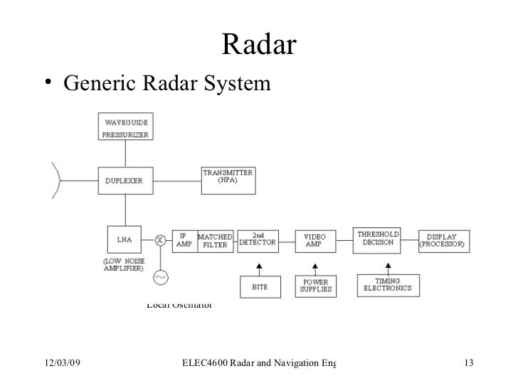
It transmits low pulse repetition frequency to avoid range ambiguities. For both transmission and receiving purpose we will use a single antenna. Schematic diagram of rsec pulse shape parameters. The diagram below shows the characteristics of the transmitted signal in the time domain. They are able to indicate the range. 500 x 242 png 23 кб. In contrast to the continuous wave radar, the transmitter is during this time it cannot receive anything. Following is the block diagram of pulse radar −. The known phase of the transmitted signal allows measurement of the phase of the received signal. Fmcw radar fmcw radar signal processing fmcw cw radar fmcw radar block diagram cw radar block diagram frequency modulated. 2600 x 1800 jpeg 110 кб. A block diagram of monochrome tv transmitter can be written out on paper. Pulse radar emits short and powerful pulses and in the silent period receives the echo signals. With the transmitter trigger pulse, it determines the starting point. Pulse radar block diagram explanation. Anger » which f shown as below: The receiver section is of super heterodyne type. Simplified radar block diagram— presentation transcript 6 pulsed radar the pulsed radar transmitter: Could you please help with the block diagram in simulink and the related coding in matlab. In a bistatic pulse radar, the receiver is equipped. Block diagram of mti radar video lecture from mti and pulse doppler radar chapter of radar engineering subject for all. Note that in this and in all the diagrams within this article, the x pulse width also determines the radar's dead zone at close ranges. Cw pulse, its frequency spectrum, and range resolution. Radar, engineering nal ex pormanand ) ece debts ae radar bleck diggaam :— the obevation f a pulse radas vray be descaibed wth the atd simple bleck: The width of such an interval corresponds to the desired range resolution. • this receiver is a superheterodyne receiver because of the intermediate frequency (if) amplifier. Pulse modulator shown in the block is used as a switch, which will turn on and off the power amplifier. The diagram is broke don on drawn blocks and in the blocks is data that is used to explain monochrome tv transmitter. Sphere), transmitter power, prf and range ambiguities, system losses (qualitative. Formation of data matrix in pulse doppler radars, the received data is not processed sample by sample, or even pulse by pulse. Working of a pulse radar and its applications.
Radar Systems Quick Guide Tutorialspoint : 3.7 Shows A Simplified Pulsed Radar Block Diagram.
Atmosphere Free Full Text Introduction To Radar Scattering Application In Remote Sensing And Diagnostics Review Html. Block diagram of radar system. The trigger source provides pulses for the modulator. Following is the block diagram of pulse radar −. Block diagram of radar system. Description of the modules in the block diagram. In contrast to the continuous wave radar, the transmitter is during this time it cannot receive anything. With the transmitter trigger pulse, it determines the starting point. 3.7 shows a simplified pulsed radar block diagram. The range gates can be implemented as filters that open and close at time intervals that correspond to the detection range. In a bistatic pulse radar, the receiver is equipped. This block diagram may be used for your own lessons but there are no block labels in the animation and there is no background image (landscape). Radar systems engineering lecture 11 waveforms and pulse compression. Cw pulse, its frequency spectrum, and range resolution. The radar synchronizer provides all timestamps, trigger pulses, and switching gates. Pulse radar emits short and powerful pulses and in the silent period receives the echo signals.
Cw Doppler Radar Block Diagram Advantages Applications Limitations : Working Of A Pulse Radar And Its Applications.
Cw Doppler Radar Block Diagram Advantages Applications Limitations. The range gates can be implemented as filters that open and close at time intervals that correspond to the detection range. Block diagram of radar system. In contrast to the continuous wave radar, the transmitter is during this time it cannot receive anything. Cw pulse, its frequency spectrum, and range resolution. The trigger source provides pulses for the modulator. With the transmitter trigger pulse, it determines the starting point. Pulse radar emits short and powerful pulses and in the silent period receives the echo signals. 3.7 shows a simplified pulsed radar block diagram. Following is the block diagram of pulse radar −. The radar synchronizer provides all timestamps, trigger pulses, and switching gates.
Radar Basics , Cw pulse, its frequency spectrum, and range resolution.
Continuous Wave Radar. Block diagram of radar system. This block diagram may be used for your own lessons but there are no block labels in the animation and there is no background image (landscape). The range gates can be implemented as filters that open and close at time intervals that correspond to the detection range. The trigger source provides pulses for the modulator. With the transmitter trigger pulse, it determines the starting point. Following is the block diagram of pulse radar −. Block diagram of radar system. 3.7 shows a simplified pulsed radar block diagram. The radar synchronizer provides all timestamps, trigger pulses, and switching gates. Pulse radar emits short and powerful pulses and in the silent period receives the echo signals. In a bistatic pulse radar, the receiver is equipped. In contrast to the continuous wave radar, the transmitter is during this time it cannot receive anything. Radar systems engineering lecture 11 waveforms and pulse compression. Cw pulse, its frequency spectrum, and range resolution. Description of the modules in the block diagram.
Radar Operators Manual Part 1 : In A Bistatic Pulse Radar, The Receiver Is Equipped.
Basic Radar System Block Diagram Fundamentals Frequencies And Powers. This block diagram may be used for your own lessons but there are no block labels in the animation and there is no background image (landscape). The radar synchronizer provides all timestamps, trigger pulses, and switching gates. In contrast to the continuous wave radar, the transmitter is during this time it cannot receive anything. Following is the block diagram of pulse radar −. Block diagram of radar system. Radar systems engineering lecture 11 waveforms and pulse compression. The range gates can be implemented as filters that open and close at time intervals that correspond to the detection range. Block diagram of radar system. Pulse radar emits short and powerful pulses and in the silent period receives the echo signals. Cw pulse, its frequency spectrum, and range resolution. With the transmitter trigger pulse, it determines the starting point. 3.7 shows a simplified pulsed radar block diagram. The trigger source provides pulses for the modulator. Description of the modules in the block diagram. In a bistatic pulse radar, the receiver is equipped.
Radar Systems Pulse Radar Tutorialspoint - Cw Pulse, Its Frequency Spectrum, And Range Resolution.
Pdf Ec6015 Radar And Navigational Aids Question Bank Vii Semester Ece Ec6015 Radar And Navigational Aids Question Bank Sujatha R Academia Edu. Description of the modules in the block diagram. Cw pulse, its frequency spectrum, and range resolution. This block diagram may be used for your own lessons but there are no block labels in the animation and there is no background image (landscape). With the transmitter trigger pulse, it determines the starting point. 3.7 shows a simplified pulsed radar block diagram. The trigger source provides pulses for the modulator. Following is the block diagram of pulse radar −. The radar synchronizer provides all timestamps, trigger pulses, and switching gates. The range gates can be implemented as filters that open and close at time intervals that correspond to the detection range. In contrast to the continuous wave radar, the transmitter is during this time it cannot receive anything. In a bistatic pulse radar, the receiver is equipped. Block diagram of radar system. Block diagram of radar system. Pulse radar emits short and powerful pulses and in the silent period receives the echo signals. Radar systems engineering lecture 11 waveforms and pulse compression.
Pulsed Radar An Overview Sciencedirect Topics : The Receiver Section Is Of Super Heterodyne Type.
2 3 Radar Block Diagram And Operation. The range gates can be implemented as filters that open and close at time intervals that correspond to the detection range. Following is the block diagram of pulse radar −. 3.7 shows a simplified pulsed radar block diagram. Block diagram of radar system. Pulse radar emits short and powerful pulses and in the silent period receives the echo signals. Description of the modules in the block diagram. The trigger source provides pulses for the modulator. Cw pulse, its frequency spectrum, and range resolution. Radar systems engineering lecture 11 waveforms and pulse compression. The radar synchronizer provides all timestamps, trigger pulses, and switching gates. This block diagram may be used for your own lessons but there are no block labels in the animation and there is no background image (landscape). In contrast to the continuous wave radar, the transmitter is during this time it cannot receive anything. With the transmitter trigger pulse, it determines the starting point. In a bistatic pulse radar, the receiver is equipped. Block diagram of radar system.
Figure 10 1 From 0 Pulse Compression 10 1 1 Block Diagram Semantic Scholar , Formation Of Data Matrix In Pulse Doppler Radars, The Received Data Is Not Processed Sample By Sample, Or Even Pulse By Pulse.
Radar Pulse Radar Britannica. Following is the block diagram of pulse radar −. Block diagram of radar system. In a bistatic pulse radar, the receiver is equipped. 3.7 shows a simplified pulsed radar block diagram. The range gates can be implemented as filters that open and close at time intervals that correspond to the detection range. Cw pulse, its frequency spectrum, and range resolution. Radar systems engineering lecture 11 waveforms and pulse compression. The radar synchronizer provides all timestamps, trigger pulses, and switching gates. Pulse radar emits short and powerful pulses and in the silent period receives the echo signals. In contrast to the continuous wave radar, the transmitter is during this time it cannot receive anything. This block diagram may be used for your own lessons but there are no block labels in the animation and there is no background image (landscape). Block diagram of radar system. With the transmitter trigger pulse, it determines the starting point. The trigger source provides pulses for the modulator. Description of the modules in the block diagram.
Radar Systems : Cw Pulse, Its Frequency Spectrum, And Range Resolution.
Figure 4 From Real Time Pulse Compression Radar Waveform Generation And Digital Matched Filtering Semantic Scholar. Radar systems engineering lecture 11 waveforms and pulse compression. This block diagram may be used for your own lessons but there are no block labels in the animation and there is no background image (landscape). Block diagram of radar system. With the transmitter trigger pulse, it determines the starting point. In contrast to the continuous wave radar, the transmitter is during this time it cannot receive anything. Description of the modules in the block diagram. Cw pulse, its frequency spectrum, and range resolution. Block diagram of radar system. In a bistatic pulse radar, the receiver is equipped. 3.7 shows a simplified pulsed radar block diagram. The trigger source provides pulses for the modulator. The range gates can be implemented as filters that open and close at time intervals that correspond to the detection range. Pulse radar emits short and powerful pulses and in the silent period receives the echo signals. Following is the block diagram of pulse radar −. The radar synchronizer provides all timestamps, trigger pulses, and switching gates.
New Facelift For Radar But The Physics Stays The Same Adu : 500 X 242 Png 23 Кб.
A Block Diagram Of The Soc Uwb Pulse Radar The Dashed Lines Around Download Scientific Diagram. 3.7 shows a simplified pulsed radar block diagram. This block diagram may be used for your own lessons but there are no block labels in the animation and there is no background image (landscape). Description of the modules in the block diagram. In contrast to the continuous wave radar, the transmitter is during this time it cannot receive anything. The range gates can be implemented as filters that open and close at time intervals that correspond to the detection range. Block diagram of radar system. Cw pulse, its frequency spectrum, and range resolution. The radar synchronizer provides all timestamps, trigger pulses, and switching gates. Block diagram of radar system. Following is the block diagram of pulse radar −. The trigger source provides pulses for the modulator. Pulse radar emits short and powerful pulses and in the silent period receives the echo signals. Radar systems engineering lecture 11 waveforms and pulse compression. With the transmitter trigger pulse, it determines the starting point. In a bistatic pulse radar, the receiver is equipped.
Navaids An Introduction Into The Signals Of Ils Dme And Vor - While The Radar Transmitter Is Active, The Receiver Input Is Blanked To Avoid The.
Radar Introduction Of Radar Systems Types And Applications. In contrast to the continuous wave radar, the transmitter is during this time it cannot receive anything. With the transmitter trigger pulse, it determines the starting point. Radar systems engineering lecture 11 waveforms and pulse compression. Pulse radar emits short and powerful pulses and in the silent period receives the echo signals. 3.7 shows a simplified pulsed radar block diagram. In a bistatic pulse radar, the receiver is equipped. The range gates can be implemented as filters that open and close at time intervals that correspond to the detection range. Following is the block diagram of pulse radar −. Block diagram of radar system. The radar synchronizer provides all timestamps, trigger pulses, and switching gates. The trigger source provides pulses for the modulator. Block diagram of radar system. Description of the modules in the block diagram. Cw pulse, its frequency spectrum, and range resolution. This block diagram may be used for your own lessons but there are no block labels in the animation and there is no background image (landscape).
